RGBW LED controller with LocoNet and DCC
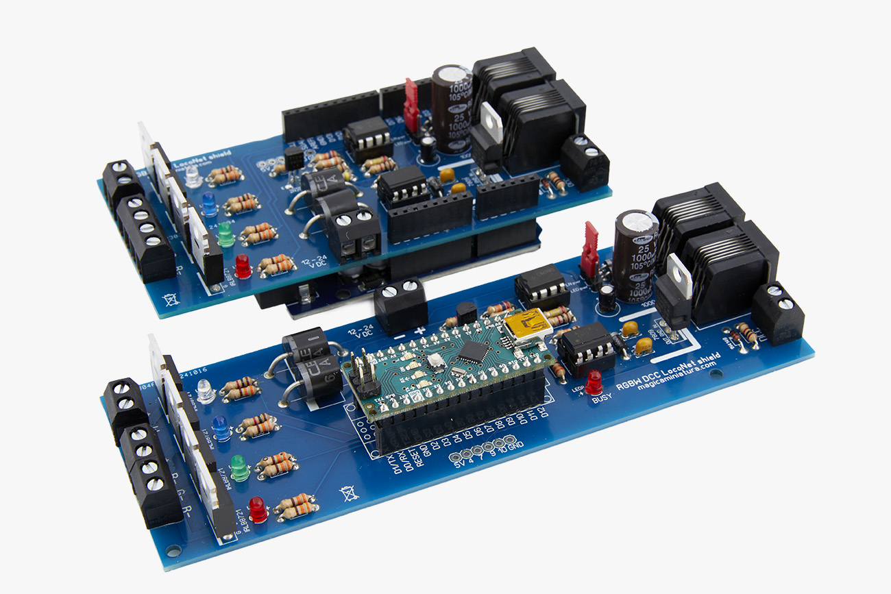
A proper model railway needs good lighting. RGBW LED strips are often used for this purpose. The great thing about these strips is that they can display various colours, allowing you to add beautiful effects to your model. For instance, you can simulate a sunrise, twilight, or a bluish night. You can even create thunderstorm effects and much more.
To control the LED strips, you'll need an LED strip controller. Often, you can buy a remote control with the strips, which is fun for selecting different colours but not very convenient for a model railway. Ideally, you would control the LED strips through your digital control centre. That's why I've put together an LED strip controller that understands both LocoNet and DCC. And it's easy to build yourself.
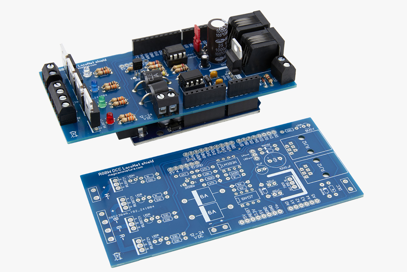
This DIY project comes in two versions: one for the Arduino Uno and another for the Arduino Nano. Aside from the size, they're nearly identical. For this project, we're using version R3, not the newer R4, due to the availability of the LocoNet library. An original Arduino costs around 25 euros, but you can get a good Chinese clone for about 3 or 4 euros.
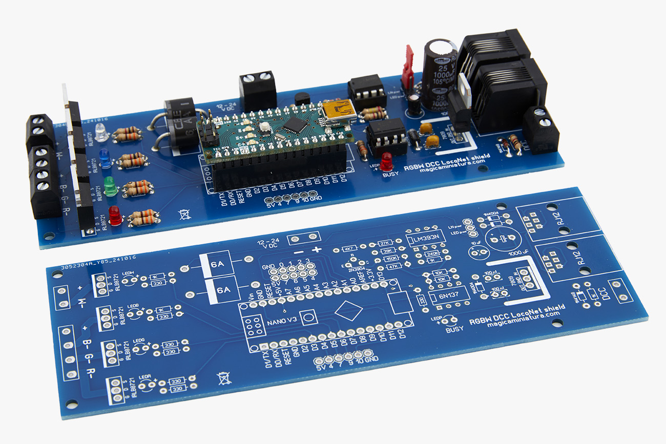
The smaller Nano mounts onto the circuit board. You can see the correct orientation on the board itself. The larger Uno sits under the board. The pin arrangement is different on each side, so it only fits one way. The official Uno and most clones have a thick USB connector, which can cause a short circuit. You'll need to insulate the metal with tape or mount the board higher using an extra set of headers. Some clones come with a smaller USB connector, which avoids this problem.
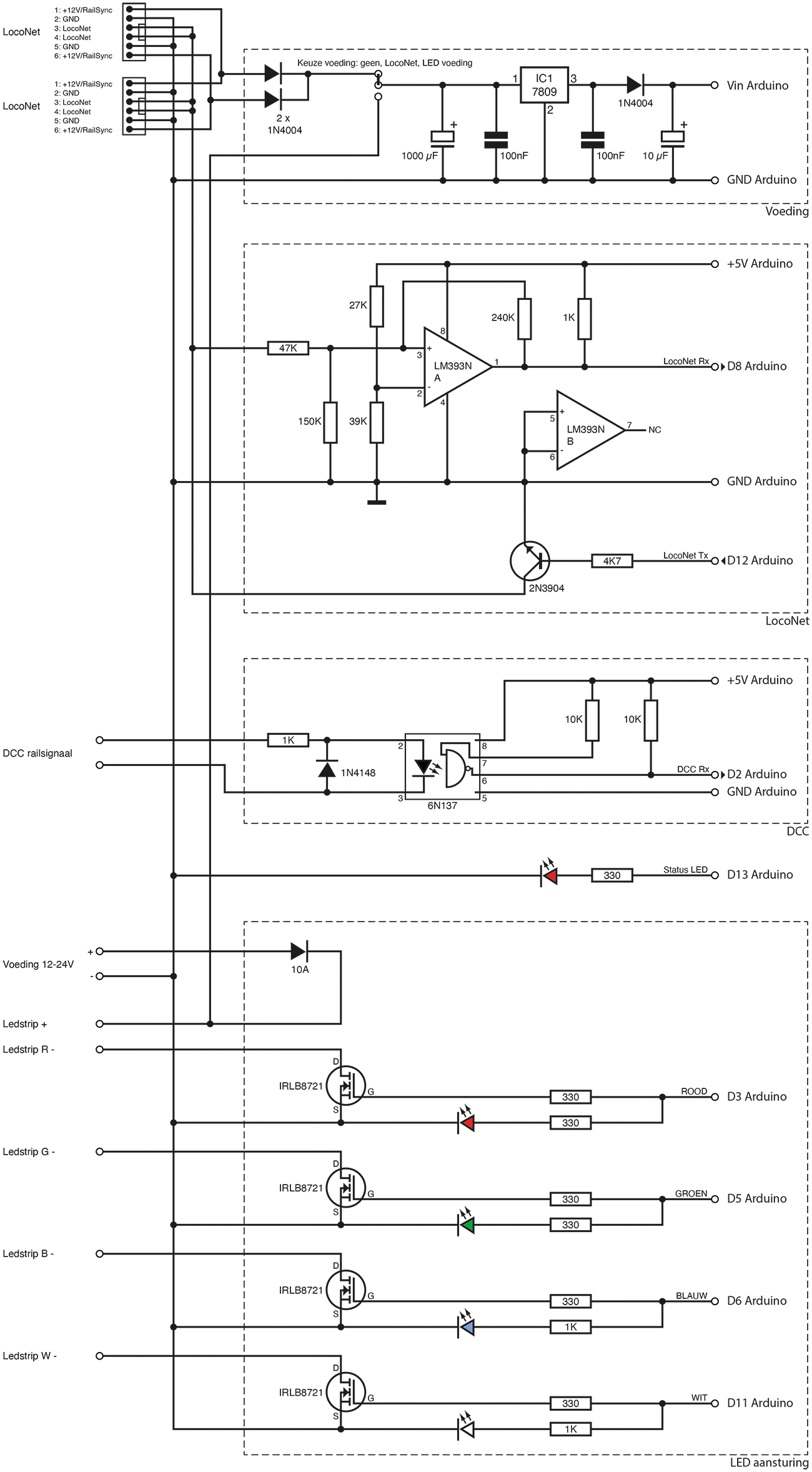
Looking at the circuit diagram, you'll see a few main blocks. The first block is the power supply. When connected to the computer, the Arduino receives power via the USB cable. Once you start using the controller, you place a jumper, and the power will come from either LocoNet or the LED strip power supply. The circuit then converts this to a stable 9 volts, which the Arduino itself reduces to 5 volts.
The second block is the LocoNet interface. This circuit adapts incoming signals for the Arduino and sends outgoing signals to LocoNet. It's a standard circuit widely used in Arduino projects. Next, we have the DCC interface. This circuit is essentially an optocoupler that relays data from the tracks without exposing the Arduino to the high track voltage. This, too, is a standard circuit.
Finally, we have a block with four MOSFET transistors to control the LEDs: one each for red, green, blue, and white. There is also a control LED, so you can see what's happening even without the LED strip connected. The fifth LED is a status LED that lights up when the Arduino is in the process of transitioning from one lighting mode to another. The PCB has connectors for both RGB and white LED strips, but you can also connect combined RGBW LED strips; in that case, you only need to use one of the positive terminals.
Although the MOSFETs can handle high power, there is a limit to the current that can flow through the PCB. This limit is around 8A-10A in total, which corresponds to 100-120 Watts for 12V strips and 200-240 Watts for 24V strips. At higher power levels, the two large diodes may become hot. Be mindful of this if you push the limits. If necessary, consider using slightly larger diodes or mounting them a bit higher for better cooling.
| Parts | ||
| Count | Description | Reichelt # |
| 7 | Resistor 330 Ohm | 1/4W 330 |
| 4 | Resistor 1 kilo Ohm | 1/4W 1,0K |
| 1 | Resistor 4,7 kilo Ohm | 1/4W 4,7K |
| 2 | Resistor 10 kilo Ohm | 1/4W 10K |
| 1 | Resistor 27 kilo Ohm | 1/4W 27K |
| 1 | Resistor 39 kilo Ohm | 1/4W 39K |
| 1 | Resistor 47 kilo Ohm | 1/4W 47K |
| 1 | Resistor 150 kilo Ohm | 1/4W 150K |
| 1 | Resistor 240 kilo Ohm | 1/4W 240K |
| 1 | Capacitor 1000 µF 25 V (rad) | RD1E108M10020180 |
| 1 | Capacitor 10 µF 25 V (rad) | KS-A 10U 16 |
| 2 | Capacitor 100 nF | Z5U-2,5 100N |
| 3 | Diode 1N4004 | 1N 4004 DIO |
| 1 | Diode 1N4148 | 1N 4148 |
| 2 | Diode 6A | P 600B |
| 2 | LED red 3 mm | LED 3MM RT |
| 1 | LED green 3 mm | LED 3MM GN |
| 1 | LED blue 3 mm | LED 3MM BL |
| 1 | LED white 3 mm | LED EL 3-2850KW |
| 1 | Transistor 2N3904 | 2N 3904 |
| 4 | MOSFET IRLB8721 | IRLB 8721 |
| 1 | Voltage regulator 7809 | µA 7809 |
| 1 | LM393N | LM 393 DIP |
| 1 | 6N137 | 6N 137 |
| 2 | IC socket 8 pin | GS 8 |
| 2 | RJ12 (6p6c) | MEBP 6-6S |
| 5 | Screw terminal 2 poles, RM 5,08 | AKL 101-02 |
| 1 | 1 x 36 header | SL 1X36G 2,54 |
| 2 | 1 x 16 female header (only Nano version) | MPE 094-1-016 |
| 1 | Stackable shield headers (only Uno version) | Webshop Magica Miniatura |
| 1 | Jumper | JUMPER 2,54GL RT |
| 1 | Arduino Uno/Nano R3 | |
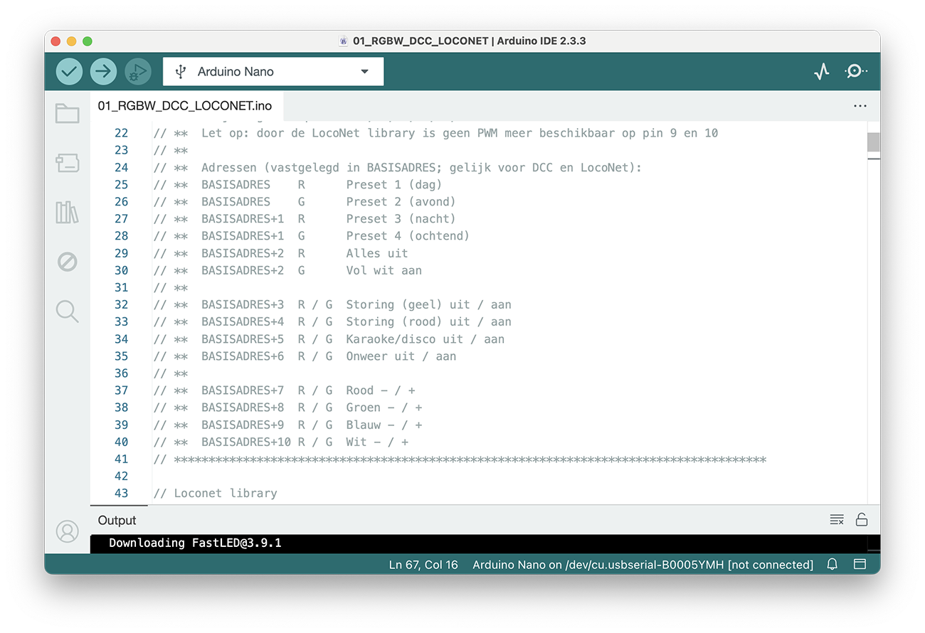
After assembling the PCB, install the Arduino development environment from the Arduino website to program the Arduino. You can download my Arduino sketch and use it. You will need to install the Loconet and NmraDcc libraries via the library manager.
The controller functions like any signal or turnout decoder: you send a red or green command to an address. The sketch specifies what each command does. You can set the base address a few lines lower in the code. By default, this is set to 101.
Note for the Roco Multimaus: the addresses are shifted by 4 (this applies to all decoders you control with the Multimaus). If the base address is set to 101, you should select address 105 on the Multimaus.
Important: This is a DIY hobby project for building and experimenting, not a thoroughly tested commercial product. Assembly and use are at your own risk.
You can order the parts from Reichelt. Here is the full parts list at Reichelt.
The PCBs can be found in the Magica Miniatura webshop.
2024